




Waste Plastic Oil Refining Equipment: A Deep Dive into Pyrolysis Kinetics, Phase Control, and Engineering Anti-Corrosion
The chemical recycling of waste plastics is fundamentally an exercise in controlled molecular scission. It employs thermal energy to sever carbon-carbon backbones, rearranging high-polymer disordered structures into a mixed system of small-molecule alkanes and alkenes. This is not incineration or gasification; it is a sophisticated physicochemical coupling project that integrates precise temperature control, multi-stage condensation, and gas-liquid-solid phase separation.
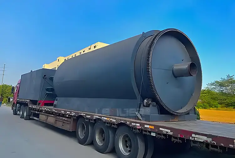
I. The Three-Stage Chemical Mechanism of Pyrolysis
The pyrolysis of waste plastics within the reactor follows strict, stepwise degradation rules, typically divided into three characteristic temperature intervals:
-
Low-Temperature Initiation (250°C – 350°C): Free-Radical Chain Scission This stage primarily involves the removal of pendant groups and chain-end scission. For Polyvinyl Chloride (PVC), this temperature window triggers the dehydrochlorination reaction, releasing substantial hydrogen chloride (HCl) gas. Polystyrene (PS) begins to depolymerize here, generating styrene monomers and oligomers. The critical control parameter at this stage is the heating rate. Too slow a rate fails to generate sufficient radical concentrations, while too rapid a rate causes localized overheating, leading to cross-linking and coking.
-
Mid-Temperature Random Scission (350°C – 480°C): Product Distribution This is the core phase where the main carbon chains undergo random scission. Polyethylene (PE) and Polypropylene (PP) follow a random scission mechanism; the carbon chains fracture at stress concentration points due to intense thermal vibration. The product distribution follows a Gaussian distribution pattern, with a higher proportion of liquid hydrocarbons in the C5 – C20 range. However, the temperature should never breach 500°C. Beyond this threshold, secondary cracking reactions intensify, drastically increasing light gaseous hydrocarbons (C1 – C4) and reducing liquid oil yield. Consequently, closed-loop PID temperature control is the foremost process parameter in the equipment's design.
-
High-Temperature Aromatization (480°C – 550°C+): Coke and Aromatic Genesis This is the temperature interval that engineers deliberately avoid. Olefins undergo Diels-Alder cyclization, dehydrogenating to form polycyclic aromatic hydrocarbons, which ultimately condense into coke deposited on the reactor walls and pipelines. Coke has a thermal conductivity roughly 1/100th that of steel, making it the direct cause of a sudden drop in thermal efficiency.
II. Core Reactor Design and Thermodynamic Engineering
Industrial continuous systems are fundamentally distinct from batch-mode furnaces. Their essence lies in the synergy of heat and mass transfer.
-
Reactor Type Selection Logic: Current mainstream equipment diverges into two primary designs. For mixed plastics with high ash and high impurity content, the rotary kiln reactor is superior. It relies on the rotation of the drum and internal lifters to toss the plastics evenly against the hot inner wall, creating a "material curtain" that significantly boosts the wall-to-bed heat transfer coefficient. For pre-cleaned, pure polyolefins, the fluidized bed reactor shows greater potential. It employs quartz sand or ceramic balls as a heat carrier, with fluidizing gas (recycled nitrogen) carrying heat to achieve isothermal operation throughout the reactor, completely eliminating localized hot spots.
-
Distillation Column Design for Multi-Stage Condensation: The oil gas exiting the reactor carries substantial aerosols and waxy components. The internal fractionating column typically employs corrugated sheet packing or float valve trays. Through precise control of the reflux ratio at the column top, countercurrent contact between the liquid and vapor phases is achieved. Leveraging differences in relative volatility, the oil gas is cut into light naphtha fractions (<170°C), middle diesel fractions (170-360°C), and heavy fuel oil fractions (>360°C). The number of trays dictates separation precision; industrial-grade equipment typically requires 15 to 20 theoretical plates.
III. Engineering Solutions for Fatal Impurities (Chlorine, Metals, Silicone)
Impurities in waste plastics are the primary cause of equipment failure. Engineering solutions must address this on two fronts: the vapor phase and the liquid phase.
-
Vapor-Phase Dechlorination – High-Temperature Absorption: The most effective method involves installing a fixed-bed reactor in the high-temperature pipeline (approximately 350-400°C) between the reactor outlet and the condenser. This bed is packed with calcium-based or sodium-based adsorbents (such as quicklime or sodium carbonate). The principle relies on a neutralization reaction, fixing HCl as solid calcium chloride or sodium chloride. This reduces the chlorine content in the oil gas to below 5 ppm before it enters the condensation system. The key to this process lies in the designed space velocity of the adsorbent bed; excessive velocity causes pressure drops, while insufficient velocity leads to incomplete absorption.
-
Liquid-Phase Demetallization and Desilication – Centrifugal Separation and Filtration: Inorganic materials like titanium dioxide (TiO₂), silica gel (desiccants), and aluminum foil residues persist as micron-sized particulates in the pyrolysis oil post-reaction. A three-stage filtration system is indispensable: Stage 1 cyclone separation (for heavy particles), Stage 2 high-temperature melt filter (with a 25μm filtration rating), and Stage 3 disc-stack centrifuge (which uses density differences to separate light oil from heavy residues).
-
Anti-Corrosion Material Engineering: Even after vapor-phase dechlorination, residual trace amounts of HCl can condense with water vapor in the downstream sections to form dilute hydrochloric acid, causing dew-point corrosion. Therefore, the fractionating column and subsequent condenser tube bundles must be constructed from duplex stainless steel (e.g., 2205) or titanium-clad composite plates. Furthermore, during equipment start-up and shutdown, thorough nitrogen purging is mandatory to prevent air ingress, which would form a corrosive mixture of sulfurous and hydrochloric acids.
IV. Recycling Non-Condensable Gases and Thermal Balance
The pyrolysis process generates 15%–25% by mass of non-condensable C1–C4 gases, primarily methane, ethane, ethylene, and propylene, with a high calorific value of 40–50 MJ/Nm³. Modern Waste Plastic Oil Refining Equipment purifies this gas and feeds it directly into the gas burner, serving as the primary heat source for the reactor.
The system's thermal balance is calculated as follows: The endothermic heat required to raise the plastics to cracking temperature is approximately 800–1000 kJ/kg. The combustion of the non-condensable gas typically covers only 70%–80% of this total heat demand. To maintain continuous steady-state operation, the equipment requires a small supplementary feed of LPG or natural gas for auxiliary combustion. A crucial engineering consideration is the flue gas waste heat recovery. The high-temperature flue gas (approximately 500-600°C) must pass through a tubular air preheater before exhaust, preheating the combustion air to 250-300°C. This single step can elevate the system's overall thermal efficiency from 65% to above 85%.
V. The Operational Stability Challenge: Coke Inhibition
Coking is the decisive factor limiting equipment lifespan and continuous run cycles. Beyond precise temperature control, three proactive engineering strategies are employed for coke suppression:
-
Hydrogen Donor Technology: Introducing a small amount of hydrogen-rich polymers (such as crumb rubber from tires) into the feed, or maintaining a slight positive hydrogen pressure, provides free hydrogen radicals to cap the unsaturated bonds created by chain scission, thereby preventing olefin polymerization.
-
In-Line Mechanical Scraping: Fitting the reactor internals with scrapers or a screw conveyor rotating at an extremely slow speed (0.5 – 2 rpm). This serves a dual purpose: advancing the material bed and continuously scraping off nascent coke deposits adhered to the reactor wall.
-
Steam Stripping: At the tail end of the reaction phase, superheated steam (300°C) is injected into the reactor. The steam gasification reaction (C + H₂O → CO + H₂) partially gasifies the deposited carbon, extending the single operational cycle duration.
Conclusion
Waste Plastic Oil Refining Equipment represents an engineering discipline centered on scission and recombination. The true measure of its technical sophistication is not defined by a singular liquid yield percentage, but by its tolerance for contaminants, its capacity for coke suppression, and the self-balancing integrity of its entire thermal system. A genuine understanding of this industrial apparatus is only achieved when one grasps the underlying logic of free-radical reactions, tray-based fractional distillation, and dew-point corrosion mechanisms elaborated above. It is a closed-loop ecosystem of chemistry, thermodynamics, and materials science.
Send Inquiry



X
We use cookies to offer you a better browsing experience, analyze site traffic and personalize content. By using this site, you agree to our use of cookies.
Privacy Policy